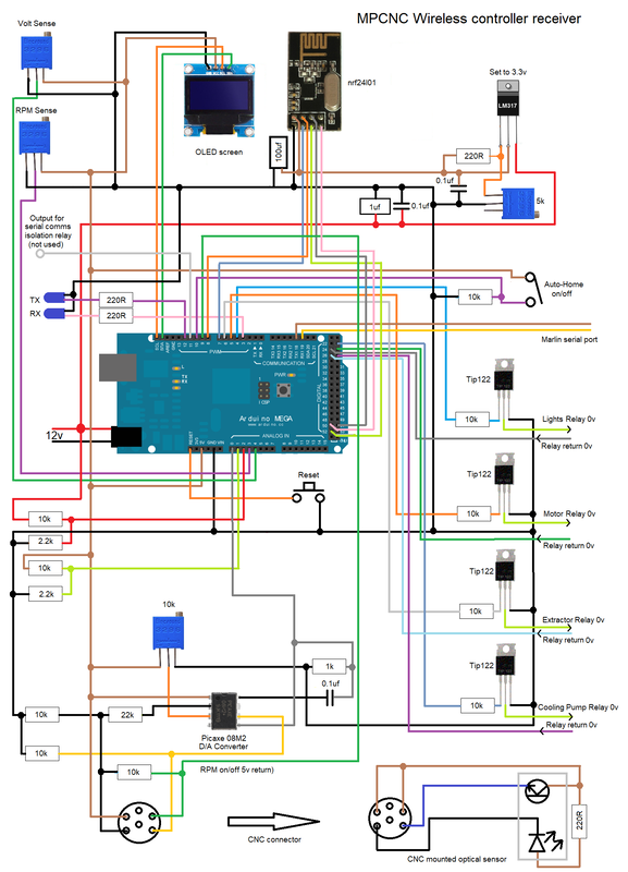
Mpcnc Wiring Diagram
If your steppers are moving the wrong direction, completely power off your board before flipping the plug over. Btt tft35 (e3) v3.0 connection diagramsnextchevron pointing right.
Hictop 3DP11 3D Printer Kit Question (Prusa i3 kit) "A13
Release notes and details are in github.

Mpcnc wiring diagram. Jerrymc3 (jerry mccarroll) january 28, 2021, 12:00am #1. In this video the wires are run and the belts are installed. Or compile and flash using platformio or arduino.
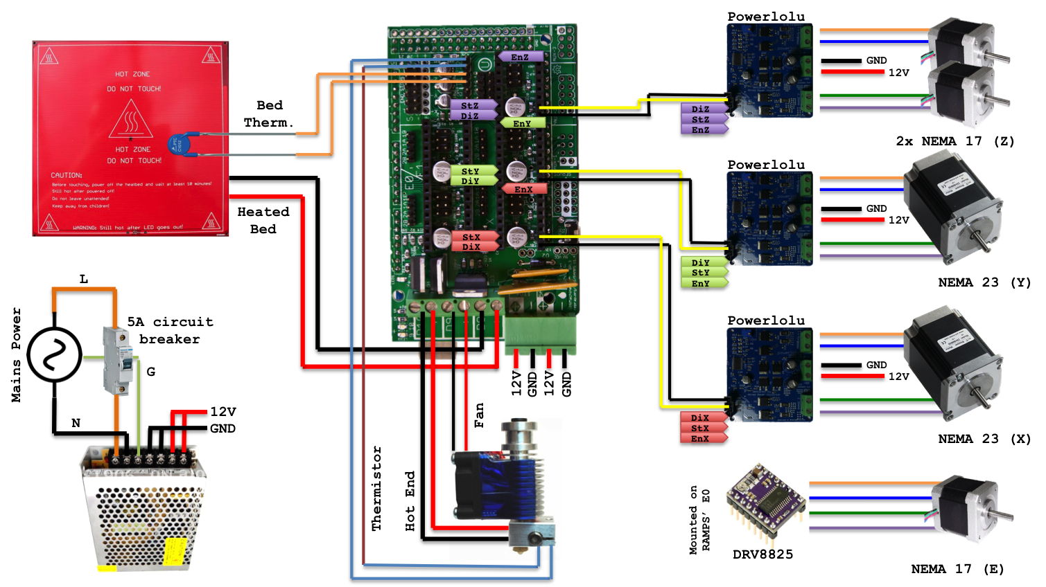
I bought the rambov1.4 board, lcd display and the complete wiring kit with end stops. The mostly printed cnc is made from 3d printed. It consists of a ramps 1.4 shield, an arduino mega 2560 board (or a clone), and a max
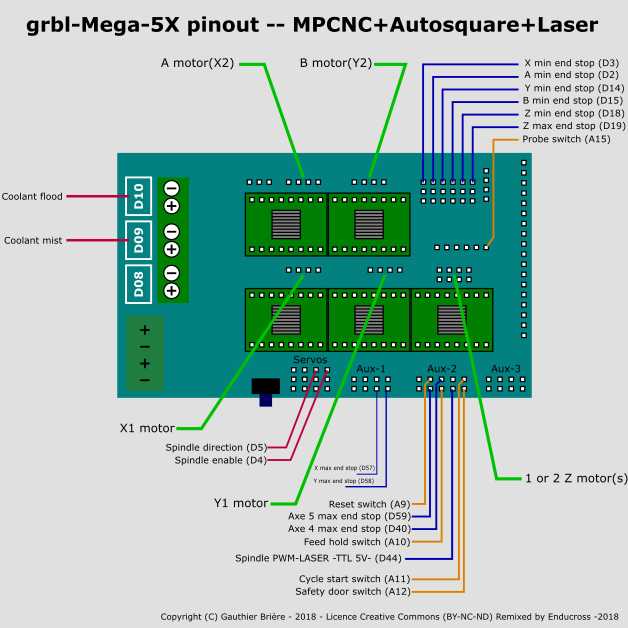
The mostly printed cnc (mpcnc) is a platform to precisely control motion. This is updated wiring kit for the lowrider cnc, and the mostly printed cnc. Matching clip side to clip side should make your stepper
This can easily be a milling machine, 3d router, 3d printer, laser cutter, vinyl cutter, cnc plasma cutter, you name it. The dual endstop firmware is on the v1 engineering marlin builder page page. I just finished the build of my mpcnc primo except for the wiring.
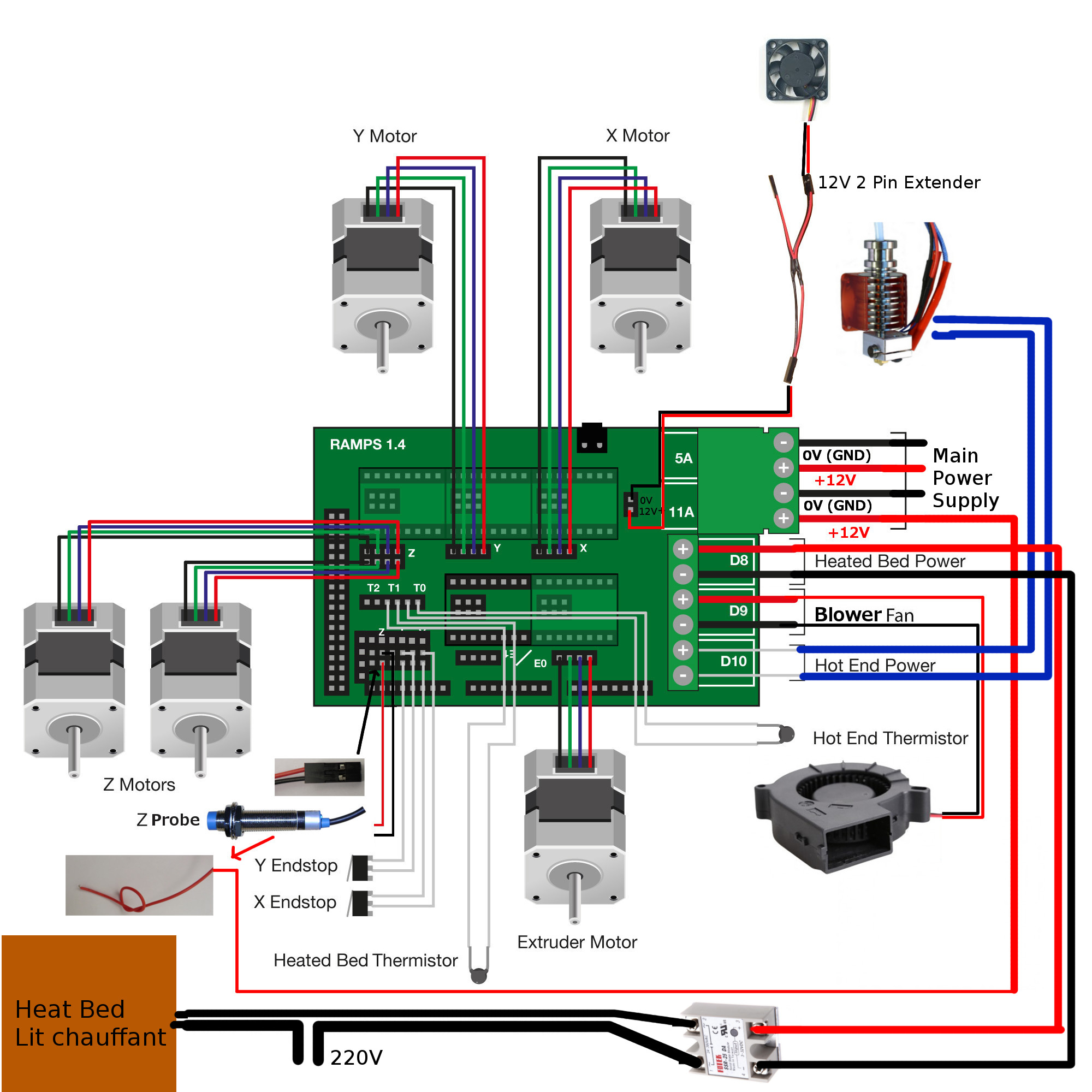
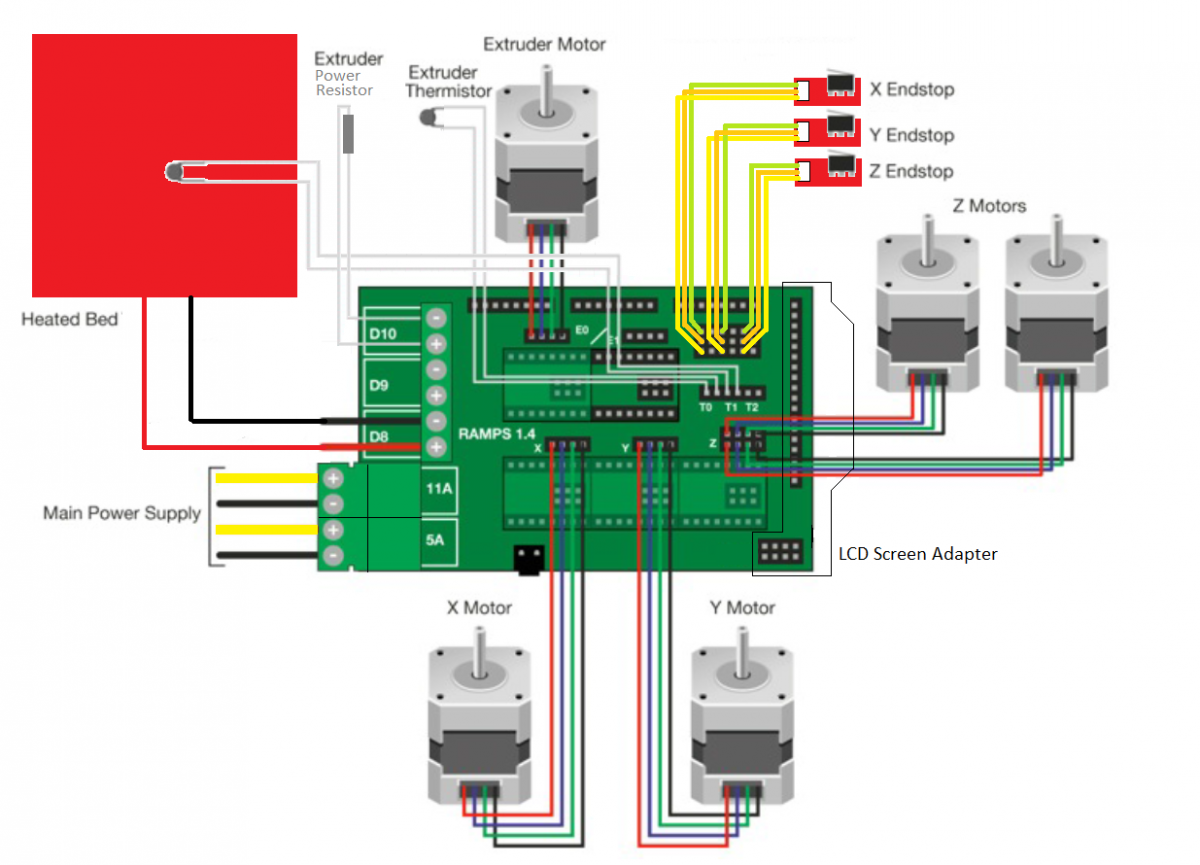
Getting to know ramps 1.4 ramps 1.4 is probably the most widely used electronics for reprap machines as of march 2014. Naturally each limit switch has two terminals, one terminal is connected to the s row, the other terminal is connected to the ground row. This is where you can download the latest configured marlin firmware for your v1engineering machines.
I made modified a few parts to keep the wiring clean, clean dual mounts. Btt tft35 (e3) v3.0 connection diagrams. 2,474 views • january 27 2020.
Oct 21, · mpcnc ramps dual endstop wiring. Parts bundle for the mostly printed cnc primo version this will work with all 3 versions, 23.5mm, 25mm, 25.4mm, of the primo mpcnc. *you will still need to buy a control board, printed parts, rails, and a spindle/tool.* *optional but recommended is an lcd as well for headless use* bundle contents part qty info nema
Remember small 1mm moves when initially powering it up, if driving your steppers the wrong way you can rip your machine apart. Assembling a mpcnc (mostly printed cnc) part 2. Here is a correct diagram of the ramps limit switch wiring that makes much more sense:
No need to crimp your own. Cost¶ all components are easily sourced, or you can. The intent of this model is provide a switched outlet for my mostly printed cnc machine (mpcnc).
Wiring diagram for mpcnc & rambo v1.4. The wiring diagram below shows how to make one outlet switched with the other being always on. V1 engineering inc | diy micro manufacturing machines and.
You should tape or otherwise secure the connections to relieve any stress of repetitive motion. I only see one output each for the x & y. I can't find a diagram to show how all this hooks up.
This puts the ramps board into 32nd stepping when using the drv8825 drivers (if you use a different driver pay attention to its orientation and step.
Electronic wiring Scalar S L XL premium 3D Modular
Kit Impresora 3d Cnc Grbl Arduino Mega Nema 17 Shield

Blog of Edward Czajka Repetier Laser Etcher
MPCNC V1 engineering Page 2 CNC Forum pour les
Chronicles of my 3D printer, part 2 the electrical
3D Printed My Electical Setup for the MPCNC by bryan_baker
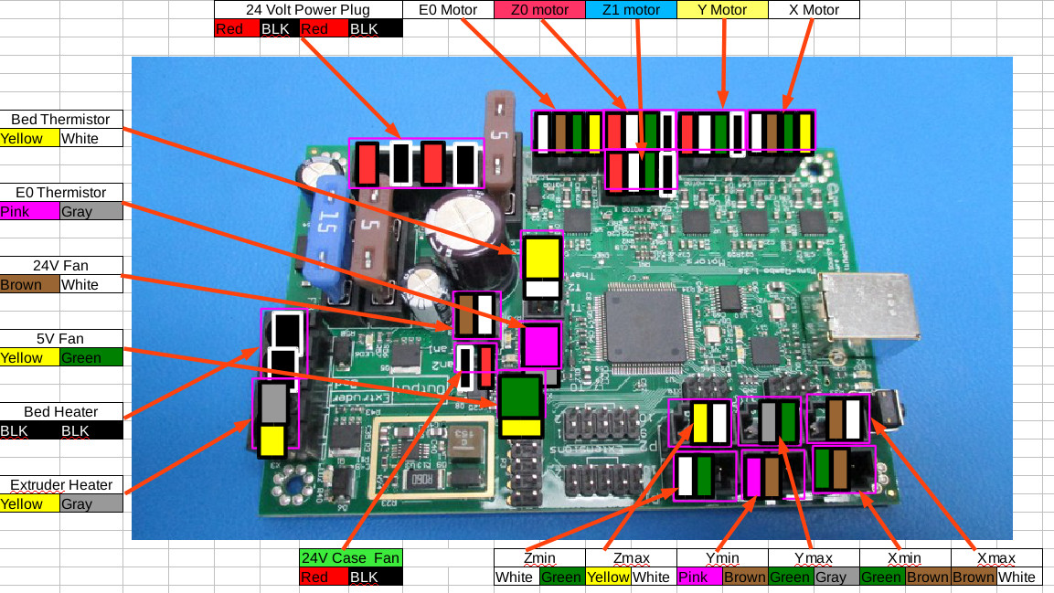
Rambo Wiring Diagram Wiring Diagram
Configuration V1 Engineering Inc
My CNC wiring SPARKY & SPECIAL EFFECTS ENGINEER.

MPCNC TOUCH PLATE PROBE WIRING V1 Engineering

RAMBo not connecting either V1 Engineering
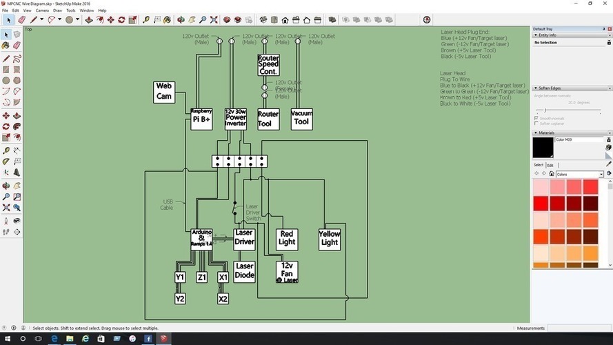
Wiring Endurance lasers to TOP popular CNC boards

Building a 3D Printer January 2015


Wiring the Steppers V1 Engineering Inc

Possible wiring of X and Y dual motors on MPCNC V1
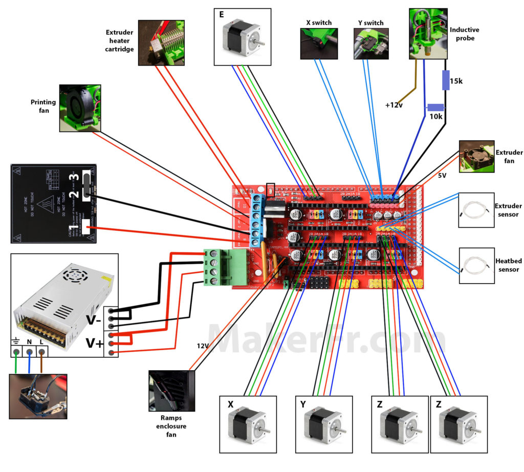
I3R Wiring MakerFr

New MPCNC build Magnolia Texas problem with ARCHIM

Wiring the MPCNC V1 Engineering Inc
My CNC wiring SPARKY & SPECIAL EFFECTS ENGINEER.